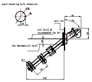
Outline and installing dimensions:


Fig.2 Dimensions of the Overall and Installation
Main technical performance:

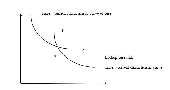
Fig.3 the fuse and backup fuse protection feature
Note: Point A: the intersection of two curves
Point B: rated minimum breaking current of backup fuse
Point C: rated maximum breaking current of fuse
During the operation, point A must be present and point B is above point A
Point C is below point A.

Fig. 4 Time - current characteristic curve
Installation and use
1. When mounting the fuse into the tank, ensure the oil level is within the range as shown in Fig. 2
2. When replacing the fuse, open the buckle on the handle and turn the handle for 90° to eliminate the adhesion between the sealing gasket and outer tube. Remove and replace the handle.
3. For the installation of three-phase fuse, replace all three phases unless you can confirm that the fault current passes through one phase.