High-voltage fuse signal indicator

Device description
The device is connected with high-voltage fuse, and able to monitor the operation of high-voltage fuse through the microswitch on the device; with the insulated flexible transmission, the mechanical force generated by striker after the fusion of fuse is transferred to the microswitch with a normally-close contact and a normally-open contact (AC 250V/5A), so that the switch converts the contact to achieve the purpose to control the signals.
The device is usually installed on the high-voltage fuse base (as shown in above figure), the dedicated connecting plate at the striker side is directly installed on the chunk screw hole, and the microswitch side may be installed on the side of floor, with the 2 × M5 screw hole at the center. They are connected with the insulated flexible connecting rod. High-voltage fuse shall not be specially processed. Plug-in and bus fuses may be directly connected. Microswitch shall be installed within 500mm to fuse according to the supply voltage of high-voltage fuse.
Manual simulation striker

Device description
Manual simulation fuse striker is used to test the mechanical reliability of linkage between the fuse striker and load switch release.
The outline dimensions of the manual simulation fuse striker are same with normal fuse as shown in the above figure. Pressing down the manual simulation striker button will make the hook come away, and the bar pops up under the action of energy storage spring. The impact energy is 1 joule.
Electric simulation striker

L=292mm,442mm,537mm
Device description
Electric simulation fuse striker is used to test the mechanical reliability of linkage between the fuse striker and load switch release.
The outline dimensions of the electric simulation fuse striker are same with normal fuse as shown in the above figure. "AC220V" power supply is applied between two contacts and output as the "DC24V" voltage of solenoid after being rectified by transformer and rectifying circuit. Solenoid is electrified and acts to make the hook come away, and the bar pops up under the action of energy storage spring. The impact energy is 1 joule.
XRNP3A accessories


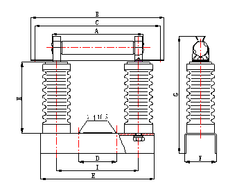
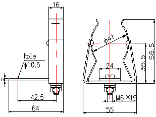
φ25.4 single fastener XRNP3A-Outline and installing dimensions of type I
Dimension parameter
Model | Outline and installing dimensions |
A | B | C | D | E | F | G | H | I |
XRNP3A-3.6~12 | 195 | 285 | 262 | 80 | 240 | 58 | 200 | 135 | 178 |
XRNP3A-24 | 324 | 416 | 393 | 160 | 400 | 80 | 312 | 220 | 308 |
XRNP3A-40.5 | 465 | 556 | 532 | 240 | 545 | 100 | 430 | 360 | 447 |


φ41 single fastener φ41 base
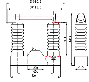
XRNT3A, XRNM3A, XRNP3A-Ⅱ and XRNC3A accessories


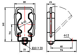
φ45 single fastener Fuse base
Rated Voltage (kV) | Standard Length L(mm) | Basic Dimensions (mm) |
A | B | C | D | E | F | G | H | φK |
7.2 | 192 | 256 | 382 | 156 | 356 | 193 | 350 | 85 | 90 | φ13 |
12 | 292 | 256 | 482 | 156 | 456 | 293 | 450 | 85 | 150 | φ13 |
24 | 442 | 336 | 632 | 236 | 606 | 443 | 600 | 85 | 240 | φ13 |
40.5 | 537 | 526 | 727 | 426 | 701 | 538 | 700 | 120 | 400 | φ17 |
Schematic diagrams of single fastener and base for fuse according to BS standard


φ76 single fastener Base (φ76)